Here I present an idea for the design of a printed circuit board Linear Induction motor that contains no ferrous magnet core material and hence, introduces no or very little hysteresis properties into the magnet circuit.
Being that this design possesses no iron constrains this device to have little ability to produce a significant linear force. In addition, this device would be limited to horizontal linear motion only. Hence, I classify this device as a positioner instead of a motor.
Also, for mechanical stability the movable and stationary members of this device (stage) would be supported by an air or magnetic bearing.
Finally, it should be noted that there is no discussion here as to the type of position feedback mechanism used. It would be assumed that this feedback would be provided by a high resolution (multiplying) linear encoder or laser interferometer.
A summary of the main components of this device is as follows, referring to Figure 1.
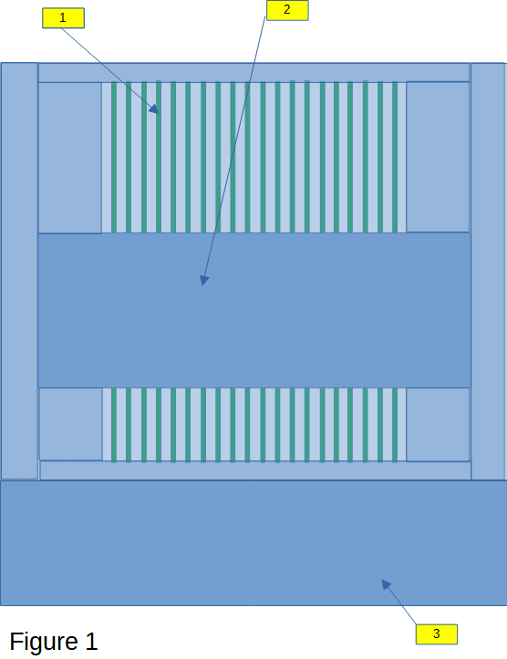
1 – An array of multilayer PC boards attached to the base of the stage interspersed between an array of aluminum fins integrated into the movable member of the stage. The PC boards contain only specially arranged layers of copper traces.
2 – The movable member of the stage is supported by an air or magnetic bearing.
3 – A compartment attached to the stage that houses all control and power electronics. Close proximity of the electronics to the stage is of paramount importance for reasons of stability.
A slice view of the stage is shown in Figure 2.
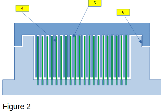
4 – The array of multilayer PC boards pressed-fit into the aluminum base of the stage. In reality this would be a tricky process affected by the height and length of travel of the stage. The higher density or number of boards would aid in the production of greater linear force. However, since there has to be an interleaving of aluminum fin between each of the boards, holding separation over the travel length of the stage becomes problematic.
5 – The aluminum fins which are machined out of block of aluminum acting as the movable member fo the stage.
6 – The air or magnetic bearing separating the base from the movable member of the stage.
Each printed circuit board contains a series of layers containing two sets of hairpin windings traversing the length of the board, connecting to the next layer and traversing back. This back-and-forth layering can be done N / 2 times where N is the number of PC board layers. In the example shown in Figure 3A and Figure 3B below, a 12-layer board is used.
One set of winding defines a overlapping for Phase A, B, C motor connections. The other winding is for a single-phase overlapping trace used to provide controlled damping.
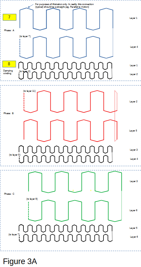
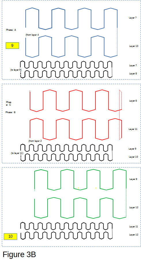
7 – For the example of Phase A connection, the winding starts at Layer 1 and returns at Layer 4 (Figure 3A). A feedthrough (via) connection is made between Layer 4 and Layer 7 (Figure 3B). Phase B and C winding layers are connected in a similar fashion.
9 – For the given PC board, Phase A ends on Layer 10 (Figure 3B). An external connection would then be made between this point and point“7” of the next adjacent board. The process is similar for Phase B and C, and repeats for K number of PC boards making up the array.
8 – For the damping winding, we start at Layer 1 and return at Layer 2 (Figure 3A). A feedthrough (via) connection is made between Layer 2 and Layer 3. This repeats from Layer 4 to Layer 5. And then from Layer 6 to Layer 7 (Figure 3B). The damping winding ultimately terminates at the return of Layer 12 denoted by point “10“. An external connection is made, and the process repeats for K number of PC boards making up the array.
Power electronics is then added to the compartment labeled “3” in Figure 1 above. This circuit is shown in the simplified block diagram of Figure 4 below.
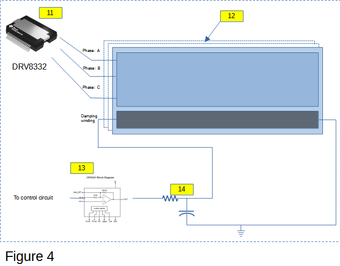
Phase connections A, B and C can be controlled using a high efficiency PWM module like TI’s the DRV8332, item “11“. PWM operation greater then 200 kHz would be required because the inherently low inductance of this motor due to the absence of ferrous material within the design. As mentioned above multiple windings are added to system by series connection of the hairpin PC board windings “12” described above.
The power component “13” used to control the damping winding must be analog by design to minimize noise impressed in the damping winding. TI’s OPA521 may be a good candidate for this design.
A filter “14” is added to the damping circuit. A large, ultra-low ESR capacitor is used to stiffen the effect of the induced eddy current in the plates caused by small movements in the tabletop. An inductor in front of the amplifier “13” could be used (not shown) to increase noise immunity in the circuit. However, it is the resistor shown in “14” that is the more important element of this circuit. This will be explained further below.
The design above can be qualified as a standard Linear Induction Motor (with poor linear force) if we remove the damping circuit. One can refer to Simulation of an Induction Motor in the Rotating and Synchronous D/Q Planes and Simulated Induction Motor Controller using a Texas Instruments C2000 motor control SOC or other numerous papers on the web that describe this.
The point of the presentation however is not strictly the use of this apparatus as linear induction motor but more as a high precision and highly stable linear positioner.
Before continuing it should be noted that there is no mention of the type of linear feedback transducer (linear encoder, laser interferometer). Needless to say, whatever would be used must exhibit high precision and stability.
The proposed linear positioning mode of this of this device is heuristic in nature and is described as follows (referring to Figure 4)..
- The transconductance control for the motor phase amplifier “11” is set at some value of constant current and is not changed during operation.
- The damping amplifier “13” is also set to some constant voltage. Current is kept under control using only the current limiting resistor of “14“. The voltage is set to allow a sufficient counter force proportional to small movements in the tabletop. The voltage (e.g., damping) applied at “13” is maintained whether the table is commanded to move or remain in position.
- Tabletop motion is controlled only by the sweeping of the three-phase frequency applied to the transconductance amplifier “11“.
- Control of motion in this precision mode is accomplished with a simple PID. However, unlike the traditional PID control, it is split into two parts, PI (digital) and D (analog). The PI term processes the difference between the command position and feedback position producing a signal proportional to the sweep frequency of for motor phase amplifier “11“. The D term is simply set to a constant which is applied to the damping amplifier “13“.
One of the most important aspects to this type of control is that the D (damping) component is not subject to the quantization error between the position command and feedback of a traditional digital closed loop system. Its effect is strictly the generation of a counter force caused by small eddy currents in the fins during motion. This ensures the highest possible stability of the table top when in the stationary position. The sensitivity of this circuit could also aid in stabilizing any small vertical oscillations at the surface of the stage caused by the air bearing itself.
As a final comment, the choice in using machined aluminum for the stage described above was for the purposes of minimizing hysteresis effects in the control loop. Also, the fins shown in Figure 2 above (labeled “5”), being aluminum would conduct current.
A possible alternative to aluminum could be low carbon steel or silicon steel which would provide greater magnetic permeability and improved force. However, using this material would require the fins (Figure 2, label “5“) to be coated with a layer of copper to allow for induced current flow.
In the case of carbon steel, it would be possible to machine the entire stage (movable and stationary) using this material. For the possible use of silicon steel which generally cannot be machined, only the fins could be fabricated with this material. In this case the fins would have to be pressed-fit into the movable member in a similar fashion as the PC boards fastened to the stationary member.
